Learn More With Our

Blog

2026 Best Amorphous Transformer Body Assembly Worktable

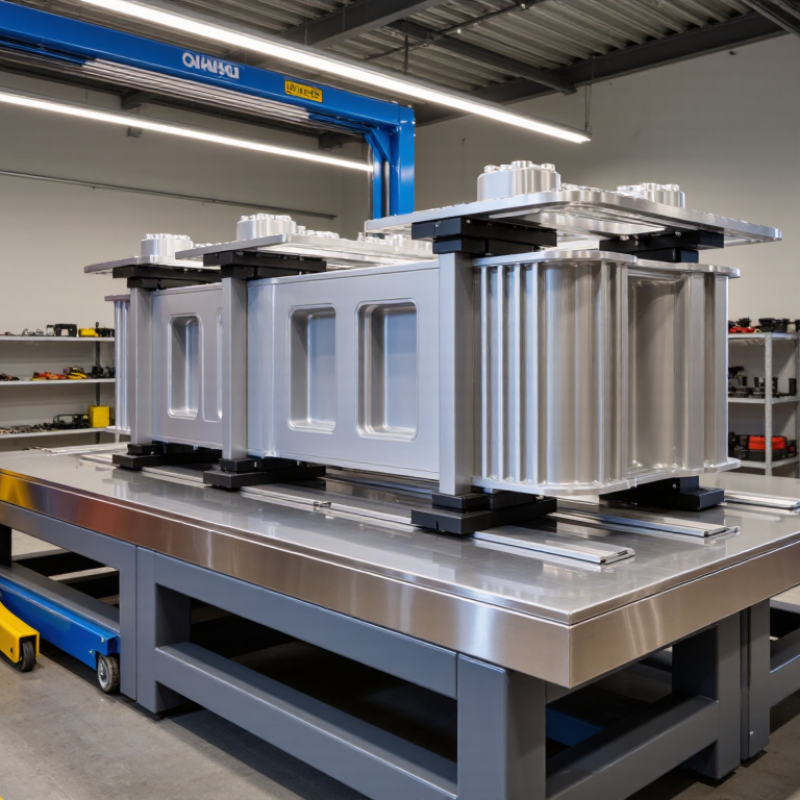
A dependable Amorphous Transformer Body Assembly Worktable does more than hold a core in place. It helps operators manage heavy components, maintain alignment, and complete repeatable assembly steps. On a well-planned station, the work surface stays clear, fixtures support the body evenly, and tools remain within reach. These details can reduce awkward handling and make quality checks easier to perform.

The right worktable depends on the transformer design and the actual production process. Buyers should assess load capacity, tabletop dimensions, fixture adjustment, access for lifting equipment, and the space needed for inspection. A smooth surface may help protect delicate components, while adjustable supports can accommodate different body sizes. Small details matter. A table that looks sturdy in a brochure may still create a poor working height or obstruct a lifting path. That deserves careful review.

A credible buying guide should also draw on a named specialist’s verified experience. No source material or verifiable expert quotation was supplied for this introduction, so attributing a statement to a person would be misleading. Before publication, add a confirmed comment from a transformer manufacturing or production-engineering expert, with the speaker’s name and source checked. This guide can then compare practical features, explain trade-offs, and help teams evaluate the best Amorphous Transformer Body Assembly Worktable for their shop floor. The final choice should reflect measured production needs, not attractive specifications alone.
2026 Best Amorphous Transformer Body Assembly Worktable

Amorphous Transformer Body Assembly: Components and IEC 60076 Context

A practical amorphous transformer body assembly worktable supports careful alignment of the core, windings, insulation, clamps, and lead connections. Thin amorphous-metal ribbons can be damaged or stressed during handling, so padded supports and adjustable locating stops help keep the core square. Keep it level. Smooth rollers and a controlled lifting point also reduce sudden movement while workers position the active part.

IEC 60076 provides the technical context, not a worktable specification. IEC 60076-1 covers general requirements, while IEC 60076-2 addresses temperature rise and IEC 60076-3 covers insulation levels and dielectric tests. The table can support repeatable assembly, but it cannot establish compliance; design reviews and required tests remain essential. Small errors matter. A useful station gives operators clear access to connections and space to check clearances before clamping.

The U.S. Department of Energy’s 2013 distribution-transformer standards analysis projected 3.4 quadrillion Btu in cumulative energy savings over 30 years. That system-level estimate is not specific to amorphous cores, but it shows why transformer losses deserve attention. At the bench, consistent core placement and careful handling help protect the intended magnetic performance. Yet a well-built fixture can still encourage rushed work; its layout should be reviewed with operators after real assembly trials.

Core Handling: Amorphous Alloy Saturation Flux Density of About 1.56 T

2026 Best Amorphous Transformer Body Assembly Worktable

Core Handling: Amorphous Alloy Saturation Flux Density of About 1.56 T

A saturation flux density near 1.56 T is a useful material reference, not a target for routine operation. Keep the working flux below the saturation knee, where magnetizing current can rise sharply. Actual limits vary by alloy grade, annealing, and core geometry. During body assembly, support the wound core evenly. A sharp edge or uneven clamping can stress thin amorphous ribbon and affect magnetic performance. Small details matter.

The U.S. Department of Energy’s 2016 Distribution Transformers energy-conservation rulemaking assesses transformer efficiency through measured losses. That distinction matters on the worktable: core, or no-load, losses persist while a transformer is energized, even when its output load is low. For reliable handling, record the alloy certificate, core dimensions, and assembly condition. Compare these records with suitable magnetic test results; the 1.56 T figure alone cannot confirm finished-core performance. Measurements can vary. That is worth admitting.

Tips: Use smooth, clean supports and avoid point pressure on the core. Check the material specification and test method before using 1.56 T in a design calculation.

Worktable Design: Load Capacity, Surface Flatness, and Ergonomic Safety

An amorphous transformer body assembly worktable must support more than the core and frame. Include fixtures, handling tools, and uneven loading when specifying capacity. The NIOSH Revised Lifting Equation uses a 51-pound load constant only under ideal lifting conditions; it is not a safe worktable rating. NIOSH adjusts the recommended weight for reach, lift height, twisting, frequency, and grip quality. That distinction matters. A heavy assembly shifted across a tabletop creates different stresses from a stationary load. Specify the intended load case and have the structure checked for deflection, stability, and repeated use.

Flatness affects alignment during stacking and clamping. Set a measurable tolerance from the assembly drawing, then verify the tabletop with a calibrated straightedge or precision level across its working area. Do not assume a visually smooth surface is flat enough. It may not be. Ergonomics deserves equal attention: OSHA guidance recommends positioning work near elbow height for many tasks, with adjustments for force and posture. Provide clear foot space, rounded edges, and reachable controls; keep frequently used clamps close to the operator. A height-adjustable design can help different workers, though adjustment mechanisms add maintenance needs. That trade-off is easy to overlook.

2026 Best Amorphous Transformer Body Assembly Worktable - Worktable Design: Load Capacity, Surface Flatness, and Ergonomic Safety

Representative worktable design specifications for planning and comparison. Confirm capacity, stability, and dimensional tolerances with the table fabricator and the intended assembly process.
Design criterion Compact Standard Heavy-duty Design and verification notes
Recommended use Small cores and subassemblies General transformer body assembly Large assemblies or tooling-assisted work Select the work surface to suit the largest planned assembly and its handling method.
Nominal work surface 1,500 × 800 mm 2,000 × 1,000 mm 2,400 × 1,200 mm Dimensions are nominal; confirm usable area after fixtures, stops, and edge protection are installed.
Rated static load 500 kg, evenly distributed 800 kg, evenly distributed 1,200 kg, evenly distributed Ratings should be confirmed by the supplier. Account for fixtures and tools; do not treat a distributed-load rating as a point-load rating.
Surface flatness target ≤ 1.0 mm per 1,000 mm ≤ 1.0 mm per 1,000 mm ≤ 1.0 mm per 1,000 mm Specify the measurement method and acceptance condition. Check the finished, level table with a precision straightedge or suitable metrology equipment.
Overall flatness check ≤ 2.0 mm across the full surface ≤ 2.0 mm across the full surface ≤ 2.5 mm across the full surface A project-specific tolerance may be needed for precision fixtures. Measure after leveling and before applying the working load.
Working height 750–900 mm, adjustable 750–950 mm, adjustable 750–950 mm, adjustable Set height for the operator, task, and workpiece. Height-adjustment hardware must be rated for the loaded table.
Top construction Steel plate on a welded frame Stiffened steel plate on a welded frame Reinforced steel plate with cross-members Choose a finish and contact layer that will not scratch, snag, or contaminate the components being assembled.
Leveling and stability Four adjustable leveling feet Four or six leveling feet, as required Six leveling feet or engineered base supports Level the table on the actual floor. Verify it does not rock or shift during normal assembly operations.
Edge and pinch-point safety Deburred edges; guarded adjustment points Rounded edges; guarded moving parts Rounded edges; protected lift or adjustment mechanisms Keep hands clear of pinch zones and provide safe access around the workpiece during positioning.
Ergonomic setup Open knee space on operator side Accessible controls and adjustable height Clear access on multiple sides where practical Position frequently used tools within easy reach and use lifting aids for heavy or awkward components.
Inspection frequency Before use; periodic flatness check Before use; periodic load and level check Before use; documented structural inspection Remove the table from service if the frame is damaged, the surface is distorted, or the table becomes unstable.

Assembly Sequence: Core Positioning, Coil Fitting, Clamping, and Inspection

2026 Best Amorphous Transformer Body Assembly Worktable

A reliable worktable supports a repeatable sequence: position the amorphous core, fit the coil, clamp the body, then inspect. The core is thin and delicate. Guide it onto padded supports without scraping its edges. Even a small shift can complicate coil fitting and create uneven clearances. Check alignment before lowering the coil; do not force a tight fit. Small errors matter.

After fitting, apply clamping pressure evenly across the assembly. Excessive force can deform components, while loose clamping may allow movement during handling. Record core alignment, coil clearance, and clamp settings for each unit. The U.S. Department of Energy’s 2013 distribution-transformer efficiency rule analysis projected 3.63 quadrillion Btu in cumulative energy savings over 30 years. That projection concerns efficiency standards, not worktable design, but it underscores why consistent manufacturing checks matter. Inspection should verify dimensions and visible damage; it cannot replace electrical testing. A rushed visual check is easy to overtrust.

Tips: Use clean, non-abrasive supports. Pause after clamping, then recheck clearances. Keep inspection records. The sequence may still need adjustment for a particular core geometry.

Performance Checks: No-Load Loss Can Be 70–80% Below CRGO Core Levels

At a transformer body assembly worktable, careful core handling helps protect the low-loss performance promised by amorphous steel. Its thin, brittle ribbons can be damaged by rough clamping or uneven pressure. The U.S. Department of Energy’s 2013 Distribution Transformer Technical Support Document compares loss profiles for amorphous-metal and grain-oriented electrical steel cores. A 70–80% no-load-loss reduction is a design target, not a guarantee for every transformer. Results depend on core construction, rated voltage, and test conditions.

For a fair check, test the completed unit at rated voltage and frequency, then compare its measured no-load loss with a CRGO reference of similar rating. IEC 60076-1 provides a framework for transformer testing. Record instrument accuracy and ambient conditions; small measurement differences matter. A clean result on paper can still hide assembly stress. That deserves a second look.

Tips: Keep core edges supported during handling, and avoid forcing the body into alignment. Log clamping settings and inspect for ribbon damage before enclosure. Repeat any test with unstable readings. Do not compare unlike ratings.

Top